How to Size an ABB KNX Bus Power Supply from Device Current and Line Layout
Size each KNX bus line using device current, then compare ABB 320 mA and 640 mA power supplies, diagnostics and line-planning considerations.
Sizing a KNX bus power supply begins with the load on each physical twisted-pair line, not with the total number of rooms or the number printed on the front of a device. For a dependable design, identify the devices powered from the KNX bus, record their manufacturers’ current-consumption values, and evaluate each line separately. The resulting current schedule helps distinguish where a 320 mA supply is appropriate and where a 640 mA model gives useful capacity for the planned equipment.
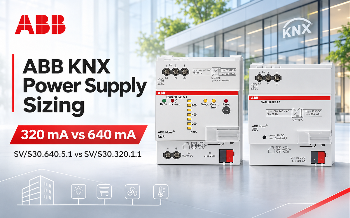
Two ABB options are the ABB SV/S30.640.5.1 and ABB SV/S30.320.1.1. Both appear in ABB’s model-specific power-supply comparison. Their rated currents differ, while the 640 mA variant adds KNX diagnostics. These characteristics should be evaluated together with the line architecture rather than treated as interchangeable features. See the ABB i-bus KNX product catalogue for the manufacturer’s comparison.
Start with a KNX line current schedule
Create a schedule for every KNX TP line showing the device identifier, its function, the bus current specified for that particular device, and the line to which it belongs. Include sensors, interfaces, actuators with bus electronics, couplers and any other devices whose KNX-side consumption contributes to that line. Distinguish KNX bus current from mains input power or a separate auxiliary supply, since these are different design quantities.
- Group devices by the KNX line actually supplying them, not merely by floor or distribution board.
- For every device, use its exact model documentation to identify the relevant KNX bus consumption.
- Add the current values for devices on each line; separately document any design allowance for future expansion.
- Review distribution, bus-cable routes and line topology alongside the calculated current before selecting equipment.
- Record the selected supply model and its rated current in the panel schedule and commissioning documents.
The straightforward sizing relationship is required line current = sum of the KNX bus currents of all devices powered on that line. This is a design calculation rather than a fixed current-per-device shortcut. A line containing a few high-consumption devices can have a different demand from a line containing many low-consumption devices. The equipment schedule, rather than device count alone, must decide the power-supply class.
ABB SV/S30.320.1.1: rated 320 mA for a planned bus line
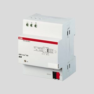
The SV/S 30.320.1.1 KNX Power Supply 320 mA is listed by ABB as a standard KNX power supply rated at 320 mA. ABB’s exact-model comparison also specifies a 30 V DC rated output, integrated choke, four modular units of installation width, and an 85–265 V AC supply input for this model. The manufacturer’s table identifies it as a modular DIN-rail component. Source: ABB i-bus KNX product catalogue.
A 320 mA unit makes sense where the documented KNX line current is compatible with its rating and the anticipated modifications are manageable. It is especially useful to differentiate a correctly sized standard supply from a diagnostic model: the decision should account not only for the initial equipment list but also for how service personnel will monitor line conditions.
For procurement, align the exact ABB type designation on the bill of materials with the product listing rather than substituting another 320 mA ABB variant. ABB lists several models with closely related names, and diagnostic capability cannot be assumed from the current rating alone.
ABB SV/S30.640.5.1: 640 mA with diagnostics
The ABB SV/S30.640.5.1 Power Supply with Diagnostics, 640 mA, MDRC carries a manufacturer-rated output of 640 mA, with a 30 V DC rated voltage and integrated choke. ABB lists its 85–265 V AC input and four-module MDRC construction in the same model comparison. Source: ABB i-bus KNX product catalogue.
In addition to its higher current rating, the SV/S30.640.5.1 includes diagnostic indications. ABB documents front-panel LED monitoring of operating and bus-load conditions, ETS communication objects for diagnostic information, and analysis using the ABB i-bus tool. The catalogue explicitly identifies bus voltage, bus current, supplementary-output current and combined current among the available diagnostic values. Source: ABB i-bus KNX product catalogue.
These functions can be useful in a distribution board serving a large or frequently modified KNX installation. During commissioning, diagnostics can help establish a documented baseline. During service, measured bus current and device status can help the engineer determine whether a fault is associated with an abnormal load, the supply, or another part of the installation. Diagnostics supplement the wiring and electrical checks; they do not replace them.
How to treat the additional voltage output
ABB documents an additional unchoked voltage output for the SV/S30.640.5.1. Its catalogue explains that supplying another KNX bus line from that output involves an additional external choke. The model’s reported total current is the sum of the bus and supplementary-output currents. Source: ABB i-bus KNX product catalogue.
For line planning, treat the unit’s 640 mA as the supply rating, not as two independent 640 mA allocations. Represent the relevant output connections and choke in the electrical diagram, and allocate the supply capacity across the intended loads. This prevents an apparently simple second terminal from being mistaken for a complete second independent source.
ABB 320 mA versus 640 mA: verified model comparison
| Manufacturer-confirmed characteristic | SV/S30.320.1.1 | SV/S30.640.5.1 |
|---|---|---|
| Rated current | 320 mA | 640 mA |
| Rated output voltage | 30 V DC | 30 V DC |
| Integrated choke | Yes | Yes |
| Mains input | 85–265 V AC | 85–265 V AC |
| DIN module width | 4 modules | 4 modules |
Both products are documented in ABB’s ABB i-bus KNX product catalogue. The higher-rated unit is the model with advanced diagnostic features in this comparison. The current rating is therefore only one part of the selection: line requirements, operational visibility and panel design may also influence the specified product.
Coordinate line architecture with the current calculation
A KNX building installation may contain several electrically separated lines and more than one power supply. A sensible design allocates devices to each line first, then calculates consumption per line and selects its supply. Adding device currents across an entire building and comparing the sum with a single power supply does not describe the actual line topology.
Where the installation uses couplers, document their position and KNX-side consumption in the line schedule. When extending an existing system, update the schedule for the complete affected line rather than counting only the new devices. This helps distinguish a local extension that remains within the existing supply budget from a redesign requiring different line distribution.
Electrical design must also account for the physical bus routing. The planned device positions, cable paths and line arrangement are relevant engineering checks independent of the supply’s nameplate current. Check the applicable KNX topology and manufacturer installation instructions before freezing the drawing, and make the final bus-voltage verification during commissioning.
Designing for expansion and maintainability
Commercial installations often evolve after initial handover: additional sensors may be added, spaces subdivided, or an interface introduced for new control functions. During design, separate the documented present load from the anticipated future load. The schedule should make the basis for the selected current class understandable to the next engineer maintaining the system.
There are trade-offs on both sides. Selecting a supply solely because it has a larger current rating may not solve a topology problem. Selecting a smaller supply based only on today’s device count may make later expansion inconvenient. The correct decision follows the documented electrical load and the intended line arrangement; diagnostics are an additional service consideration, not a substitute for capacity planning.
Commissioning checks before handover
- Check the installed part number against the bill of materials and the KNX line diagram.
- Confirm that the bus conductors and line connections correspond to the planned topology.
- Verify the actual line consumption and bus voltage under normal operating conditions.
- On a diagnostic-equipped supply, record available current and status information as a commissioning baseline.
- Update the device-current schedule and label each panel and bus line for future service.
The SV/S30.640.5.1’s diagnostic interface makes ongoing observation of the supply useful where maintenance teams need operational visibility. The SV/S30.320.1.1 can meet the electrical requirement for a line whose documented demand fits its 320 mA rating. In either case, safe and dependable operation depends on sound electrical design, correct wiring and practical handover records.
Choosing the appropriate ABB KNX supply
Start with the per-line current schedule. Choose the ABB 320 mA power supply when the specified line load suits that rating. Consider the ABB 640 mA diagnostic power supply when the higher rated output and documented diagnostics fit the project requirements. For product availability and related devices, browse ABB KNX products and the Power Supplies & Line Couplers category.
For a robust bill of materials, identify the exact model, the corresponding KNX line, the calculated load and the reason for selecting that power-supply class. This makes the design decision reviewable at tender stage and useful during installation, commissioning and future maintenance.