Selecting a GEWISS KNX Switching Actuator for Lighting and Electrical Loads
Compare GEWISS GWA9108 and GW90741 by channels, contact ratings, KNX features and panel space. Select the right actuator for lighting circuits.
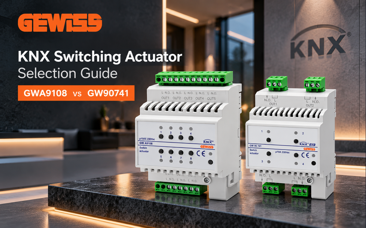
Choosing between the GEWISS GWA9108 and GW90741
Selecting a GEWISS KNX switching actuator begins with the number of independently switched circuits, the nature of the connected loads and the available distribution-board space. The GEWISS GWA9108 8-Channel KNX Switching Actuator 10AX and GEWISS GW90741 4-Channel 10A KNX Switching Actuator (4 DIN Modules) address different circuit counts and carry different manufacturer contact designations. They should therefore be specified against a circuit schedule, rather than treated as interchangeable solely because both are DIN-rail KNX switching actuators.
The most useful first decision is whether the design needs four separately controlled outputs or eight. The next is whether each actual load is suitable for the precise switching-contact designation associated with the selected model. A lighting schedule, panel layout and intended control sequence together provide a more reliable purchasing basis than a single nominal current figure.
GEWISS GWA9108: eight outputs in four DIN modules
The GEWISS GWA9108 has eight switching channels, with manufacturer-listed output contacts of 8 NO, 10 AX, 230 V AC. Its enclosure occupies four DIN modules, uses DIN-rail mounting and carries an IP20 rating. These details are recorded on the official GWA9108 product page.
For a project schedule with several independently switched lighting circuits, eight outputs within a four-module actuator can make the GWA9108 an efficient panel-layout candidate. Count only circuits that actually require independent relay commands; several luminaires controlled together may form one switching group, whereas separately scheduled zones must remain separate. This distinction determines useful channel demand before any actuator is ordered.
Local switching and visible output status
The GWA9108 technical manual describes eight front push-buttons that directly activate the load-controlling relays and eight green LEDs indicating output activation. These front-panel facilities can be useful when checking which controlled output has been commanded during commissioning or troubleshooting. Consult the GWA9108 technical manual for the documented behaviour of these controls; the indicators should not be interpreted as a substitute for checking the electrical condition of the connected load.
Channel behaviour for KNX sequences
For the GWA9108, the technical manual identifies ON/OFF switching, selectable normally open/normally closed contact behaviour, status reporting, relay-state handling after bus-voltage failure or recovery, switching delays, timed staircase-light operation with possible switch-off warning, cyclic flashing and scenes. The manual also describes configuration of up to eight scenes per channel. These are relevant distinctions when a lighting specification calls for more than simple on/off commands.
Consider the intended sequence for every channel. A corridor may call for timed operation, while a group of general lighting circuits may participate in scenes. Bus-failure and recovery behaviour deserve deliberate coordination with the project’s operational requirements. Confirm the selected application configuration during ETS engineering before promising a particular sequence to the client.
When GWA9108 is the practical choice
- The circuit schedule requires up to eight independently switched outputs from one actuator.
- Four-module DIN-rail space is available for this device.
- The control design can take advantage of the documented front controls, status LEDs or channel functions.
- The specified connected loads are suitable for the GWA9108 contact rating and switching duty.
An eight-output device is not automatically the most economical design where only a small number of independent circuits are needed. Channel capacity should be matched to the real panel schedule, with allowance for future changes assessed separately from the present requirement.
GEWISS GW90741: four outputs with a defined AC1 rating
The GEWISS GW90741 provides four output channels. The manufacturer specifies 4 NO, 10 A (AC1), 230 V AC contacts and a rated switching current of 10 A at cos φ = 1. It is a four-DIN-module, DIN-rail-mounted unit with an IP20 rating. See the official GW90741 product page for the recorded electrical and mechanical data.
A four-output circuit plan may favor this model when each switching group is clearly defined and additional outputs would not be used. Because it occupies four DIN modules, panel capacity must be calculated from the actual device allocation rather than assuming that fewer outputs necessarily mean a narrower actuator. The output count, space commitment and load type are separate selection criteria.
KNX bus and installation considerations
The GW90741 is specified for a KNX TP1 interface, supplied via the KNX bus at 29 V DC SELV, with maximum bus current of 5 mA. Its connection information identifies a KNX bus terminal, screw-type wiring terminals and a stated terminal capacity of up to 4 mm². These details help the designer plan bus power and termination arrangements; the manufacturer data are available on the GW90741 product page.
The specified operating temperature range for the GW90741 is −5 °C to +45 °C, and its stated humidity limit is 93% maximum. Its IP20 classification makes enclosure selection and installation environment part of the design review. Consider the real ambient conditions of the distribution board, not only the nominal room temperature.
GW90741 load selection
The GW90741 manufacturer data include a compact fluorescent load entry of 8 × 23 W. This is a particular documented load category, not a universal allowance for all lighting drivers. Likewise, the 10 A AC1 contact classification should not be read as a guarantee of suitability for every LED driver, transformer, capacitive input or motor load. The switching load must be assessed by its actual electrical characteristics and the manufacturer’s applicable limits.
For a four-circuit installation, this actuator can be a sensible candidate when its specified contact duty is compatible with the intended circuits. Where load behaviour or switching duty differs from the documented classification, choose a properly rated switching solution rather than relying on the number printed next to the relay contacts.
GWA9108 vs GW90741: verified technical comparison
| Verified attribute | GWA9108 | GW90741 |
|---|---|---|
| Independently switched outputs | 8 channels | 4 channels |
| Manufacturer contact designation | 8 NO, 10 AX, 230 V AC | 4 NO, 10 A (AC1), 230 V AC |
The output-count distinction is straightforward; the switching classifications need more care. 10AX and 10 A (AC1) are not interchangeable statements about every possible load. In particular, neither designation alone establishes how many electronic lighting drivers may be connected to a circuit. Review the load-specific limits before committing either model to a lighting package.
Both products are listed as four-module DIN-rail devices with IP20 protection. Because those attributes are shared, they do not distinguish the products in the comparison table; they remain relevant to board layout and enclosure selection.
A practical specification workflow for lighting and electrical loads
1. Build the switching schedule before selecting the actuator
List each separately controlled circuit and label it by location, use and intended control group. A useful schedule distinguishes normal lighting, timed lighting, special operating modes and other electrical loads. Decide whether multiple fixtures switch as one circuit or require independent outputs. This avoids buying an eight-channel actuator for four control groups simply because eight luminaires appear in the drawing.
2. Classify connected equipment, not just its total wattage
Identify the devices connected to each relay output, including their electrical input characteristics and switching frequency. Electronic lighting equipment can present a brief startup demand very different from its steady running current. Before final selection, check the combined driver inrush and intended switching duty against the manufacturer’s permitted load-specific switching limits for the exact SKU. This verification is especially important when several drivers share one output.
3. Confirm space and installation conditions
Reserve four DIN modules for either device, then account for cable routing, protective equipment and the distribution board’s layout requirements. IP20 should be considered as a device protection rating, not a substitute for an appropriately selected electrical enclosure. For GW90741, check the documented operating-temperature range against the expected panel environment.
4. Match KNX functionality to the control narrative
Separate basic switching requirements from advanced sequences. For GWA9108, documented functions include delays, timed staircase operation, scenes, status reporting and settings related to bus-power events. If such functions are important to acceptance testing, express the required behaviour explicitly in the control narrative and commission against the relevant manufacturer documentation. Do not assume that one SKU duplicates the application functions documented for the other.
5. Prepare the procurement list by exact SKU
State the selected article number alongside the number of controlled circuits and relevant load classification. Separate procurement of the switching actuator from any protective or interface equipment determined by the electrical design. Exact SKUs matter because apparently similar product families can have different contact designations, channel counts and application capabilities.
Where a standard KNX switching actuator is a poor fit
A relay switching actuator is intended for switching circuits; it is not a substitute for continuous light-level adjustment. Where the lighting design calls for smooth dimming rather than on/off control, specify an appropriate dimming or lighting-control solution. Similarly, switching particularly demanding electrical loads may call for a separately rated contactor or an alternative interface, selected against the equipment’s actual electrical requirements.
The products reviewed here should also not be selected simply to provide more outputs than an installation can sensibly cable or maintain. If circuits have incompatible load types, or require different handling in abnormal supply conditions, evaluate those needs circuit by circuit rather than forcing them into one undifferentiated relay schedule.
Which GEWISS KNX switching actuator should you order?
Choose the GWA9108 when eight independent switching outputs and its documented channel-control facilities suit the intended design, subject to confirmation of the 10AX contact duty for each connected load. Choose the GW90741 when four outputs are sufficient and the 10 A AC1 contact specification matches the circuit design. Both require four DIN modules, so output count—not cabinet-width reduction—is the immediate distinction between them.
For product selection and purchasing, compare the GWA9108 product listing with the GW90741 product listing. You can also explore Switching Actuators and the wider GEWISS KNX products range. A correctly documented circuit schedule will make the eventual selection more defensible for procurement, installation and commissioning.