GEWISS KNX Switching vs Dimming Actuators: Project Selection Criteria
Compare KNX switching and dimming, with verified GWA9303 RC/L load limits, LED compatibility, ETS control and installation considerations.
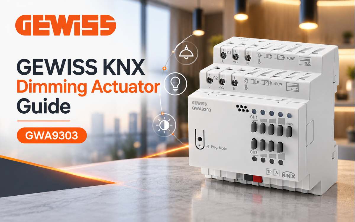
Choosing between KNX switching and dimming is a lighting-design decision, not simply a choice between two types of actuator. Switching provides a controlled ON/OFF state; dimming must also control the light output across a usable brightness range. For GEWISS projects, the GEWISS GWA9303 KNX 2-Channel Universal Dimming Actuator is a specific phase-cut dimming option when the selected lamps, drivers and intended operating modes are compatible. The key selection questions are the load technology, dimming method, allowable power for that method and commissioning behaviour.
Switching Versus Dimming: Specify the Lighting Outcome First
Use a switching actuator when the circuit needs only energisation and de-energisation, such as a non-dimmable luminaire circuit or a load controlled solely by an ON/OFF command. Switching does not create a usable variable-light output. Use a dimming actuator when occupants need gradual brightness changes, ambient scenes or adjustable local lighting. The dimming actuator must match the electrical interface expected by the luminaire or driver; a dimmable marketing label alone is not an adequate design criterion.
For a professional KNX panel schedule, document each circuit separately: the intended lighting function, lamp or driver model, control method, total connected load, minimum operating load, circuit supply and required group-address behaviour. That schedule should be completed before selecting the actuator. A simple switching duty may be a poor economic and engineering fit for a universal dimmer because the additional dimming functionality is unused and load compatibility still requires analysis.
GEWISS GWA9303: Two-Channel Universal Phase-Cut Dimming
The GEWISS GWA9303 manufacturer product page identifies GWA9303 as a KNX dimming actuator with two output channels, a 230 V AC / 50 Hz supply and a four-module DIN-rail format. GEWISS states a maximum headline power of 400 W per channel, but the operative limit changes with load type and phase-control mode. This is especially important for LED lighting, where a rating applicable to one phase-cut method must not be transferred to another.
Leading-Edge and Trailing-Edge Control
The GWA9303 technical manual describes automatic load recognition and selectable load responses. In RC operation, the dimmer uses trailing-edge phase control for resistive or capacitive applications such as suitable dimmable LEDs and electronic transformers. The L setting uses leading-edge phase control for inductive loads, including suitable wound transformers. This does not mean every LED driver or transformer will operate correctly with both methods. Select the mode according to the actual luminaire specification and the dimmer manual.
Automatic recognition can assist commissioning, but it is not a substitute for confirming the intended phase-cut interface. A 0–10 V, DALI or other separately controlled driver should not be connected on the assumption that all products described as dimmable accept phase-cut control. Where the design requires an external lighting-control protocol, choose a gateway or actuator engineered for that interface instead.
Maximum Loads Depend on Dimming Mode
The detailed GWA9303 technical-data table distinguishes between RC trailing-edge and L leading-edge operation. For adjustable 230 V LED lamps, it lists 400 W per channel in RC mode but 60 W per channel in L mode. For adjustable energy-saving lamps, the corresponding entries are 400 W and 80 W per channel. These are mode-specific upper limits rather than permissions to connect any mixture of lamps at the stated wattage.
| Verified GWA9303 characteristic | Documented value |
|---|---|
| Independent output channels | 2 |
| Adjustable 230 V LED lamps, trailing-edge RC | 400 W per channel |
| Adjustable 230 V LED lamps, leading-edge L | 60 W per channel |
| Adjustable energy-saving lamps, trailing-edge RC | 400 W per channel |
| Adjustable energy-saving lamps, leading-edge L | 80 W per channel |
| Minimum load | 5 W |
| Panel width | 4 DIN modules |
The manual also provides parallel-channel ratings: for adjustable 230 V LED lamps, 800 W in RC mode versus 120 W in L mode; for adjustable energy-saving lamps, 800 W in RC mode versus 140 W in L mode. Parallel configuration is a way to supply a single load according to the approved wiring arrangement, not a method for gaining additional independently controlled circuits. The installation guide requires both paralleled channels to operate on the same phase.
Evaluate LED Drivers Before Assigning a KNX Dimming Circuit
An LED circuit may have relatively low steady-state consumption but still be unsuitable for a given phase-cut controller. Before ordering the GWA9303, verify the actual lamp or driver is designated for leading-edge or trailing-edge dimming, and check the number of drivers, their inrush behaviour and the manufacturer-approved loading against the selected GWA9303 operating mode. For mixed batches or changed luminaires, recheck the circuit rather than assuming that the original calculation remains applicable.
The five-watt documented minimum is relevant to small architectural fixtures, decorative loads and circuits consisting of only a few lamps. Operation outside the intended minimum or maximum range can make commissioning unpredictable. In practice, test the full intended dimming span with the actual luminaire type, noting any flashing, drop-out, delayed start or inconsistent low-end brightness. Set a sensible minimum dimming level in ETS if the lamps do not behave well at the bottom of the command range.
Commissioning GWA9303 in ETS
GWA9303 provides KNX communication objects for basic switching, relative dimming and absolute brightness commands. The technical manual documents 1-bit switching (DPT 1.001), 4-bit brighter/darker control (DPT 3.007) and 8-bit brightness values (DPT 5.001). These functions can support wall push-buttons, central control and percentage-based lighting scenes, provided the ETS application is configured to the project requirements.
- Assign the channels to the lighting circuits in the approved electrical schedule and check whether they remain independent or must be wired as a manufacturer-approved parallel pair.
- Confirm the connected lamp type and configure automatic or appropriate load-response mode.
- Define a practical minimum brightness and the desired ramp behaviour, then test both switch-on and switch-off transitions.
- Configure group addresses for switching, relative adjustment, absolute brightness and any necessary status feedback.
- Review the required response to bus interruption, power restoration, locks, forced operation and scenes before handing over the system.
The device offers local manual control and channel-status indication, useful when checking circuits at the distribution board. However, the technical manual notes that bus telegrams are ineffective while manual operation is active. The panel handover procedure should therefore include returning the actuator to normal bus control after local tests.
Panel Design and Installation Constraints
The GWA9303 is intended for closed, dry indoor locations. Its manual specifies IP20 protection and an ambient operating range of −5 °C to +45 °C. The GWA9303 installation guide directs installers to maintain 8 mm ventilation clearance at both sides and to isolate mains power before installation or maintenance. It also prohibits mixing wound and electronic transformers, or energy-saving lamps and LED lamps, on the same channel. These limitations should be reflected in the panel design and the final circuit schedule.
Allow sufficient room in the panel not only for the four-module body but also for the required air gaps, cable routing and access to its local controls. Treat the dimmer as a power-control component: correct protective devices, segregation, earthing and terminations remain the responsibility of the electrical design and applicable installation rules.
When a GEWISS Universal Dimmer Is the Wrong Choice
- ON/OFF-only circuits: choose a correctly rated switching solution if no adjustable light output is required.
- Dedicated DALI or 0–10 V driver interfaces: select a control device that explicitly supports the driver interface rather than applying phase-cut dimming to the supply.
- Incompatible or non-dimmable luminaires: do not assume a universal dimmer will make a load dimmable.
- Oversized or mixed lamp circuits: divide and redesign the circuits or select equipment rated for the actual control method and load composition.
- Outdoor or harsh enclosures: account for the IP20 indoor operating limits through an appropriately engineered enclosure or a different product.
GEWISS KNX Dimming Actuator Selection: A Practical Decision
For a project needing two independently adjustable phase-cut lighting circuits, GWA9303 is worth considering when the actual luminaires fit its supported RC or L control modes and the corresponding load limits. For fixed-output circuits, start instead with switching actuation. Compare suitable products in the Dimming Actuators category and explore other GEWISS KNX products before finalising the bill of materials.
A good selection outcome is not simply choosing the largest headline wattage. It is documenting the lamp interface, checking the mode-dependent load limits, providing the proper wiring and panel ventilation, and demonstrating stable dimming in ETS with the actual luminaires. Those checks turn an actuator selection into a reliable lighting-control design.