Selecting an EAE KNX Switching Actuator by Circuit, Load and Channel Count
Compare EAE SW108, RCU0800, RCU1200, RCU1600 and RCU2000 for KNX switching circuits, relay outputs, load planning and room control.
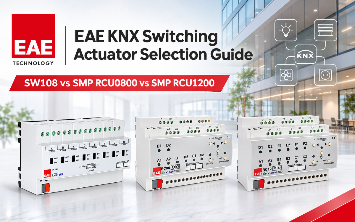
Selecting an EAE KNX switching actuator starts with the circuit schedule, the required number of independently controlled loads, and the switching behaviour of each load. A relay count is only the beginning: the designer must also separate lighting circuits from blind motors, fan-coil functions and valve control. EAE offers a dedicated eight-output switch actuator alongside room control units that combine switched outputs with selectable room-automation functions.
For panel schedules and purchase specifications, compare the EAE SW108 8-Channel KNX Switch Actuator with the RCU models using their actual output arrangements, not just their product names. The official SW108 product manual and RCU series datasheet provide the technical basis for this guide.
Begin with the circuit schedule, not the actuator name
Prepare one row per physical circuit, identifying its distribution-board location, load type, operating voltage, control purpose and required feedback behaviour. Record whether the circuit must be switched individually, paired with another output for directional control, or assigned to a room-level sequence. This creates a direct mapping between the electrical design and the actuator output terminals.
- Group independent on/off lighting circuits according to the loads they control, while retaining the individual output identity for troubleshooting and commissioning.
- Treat blind or shutter motor control as a coordinated function requiring the correct output arrangement and interlocking, rather than allocating unrelated relay outputs arbitrarily.
- Identify fan-coil and valve circuits separately. Their control mode, load behaviour and safe operating sequence must guide actuator selection.
- Mark shared services, emergency circuits and loads controlled by separate electrical protection. Their switching strategy must follow the electrical design and applicable regulations.
A precise circuit schedule also makes future changes easier: when a partition moves or a hotel room configuration changes, each KNX group address can still be traced to an electrical terminal and a physical load.
EAE actuator output comparison
EAE’s exact-model documentation distinguishes the SW108 switch actuator from the RCU room control units. The RCU output totals refer to physical relay outputs, while several room-control functions use coordinated groups of those outputs. The figures below are model-specific output totals and contact types, not a guarantee that every output can serve any function simultaneously.
| Exact model | Relay outputs | Contact type | Product role |
|---|---|---|---|
| SW108 | 8 | Potential-free bistable relay | Dedicated switch actuator |
| SMP RCU0800 | 8 | Potential-free bistable relay | Room control unit |
| SMP RCU1200 | 12 | Potential-free bistable relay | Room control unit |
| SMP RCU1600 | 16 | Potential-free bistable relay | Room control unit |
| SMP RCU2000 | 20 | Potential-free bistable relay | Room control unit |
The output totals for the RCU models are identified in the RCXXYYv2 model table and on the relevant manufacturer product materials. EAE identifies the SW108 as an eight-channel switch actuator with bistable, potential-free contacts in its SW108/SW104 R3.0 technical manual.
Choosing the SW108 for straightforward switched circuits
The SW108 is a focused option for projects that need eight independently configurable relay outputs. The manufacturer describes manual switching with slide controls for each relay and a KNX application with staircase, priority, threshold, logic and sweep functions. That combination supports a conventional distribution-board approach in which each switched circuit is assigned its own control and feedback plan.
EAE specifies 8 outputs, potential-free bistable contacts and a 16 A / 20 AX contact class in its model-specific manuals. The official SW108 product page also identifies high-inrush switching capability for relevant applications. The electrical designer must still evaluate the lamp driver or ballast manufacturer’s inrush data against the actuator contact ratings, because running current alone does not describe the complete switching duty.
A potential-free relay contact does not supply a load on its own. The electrical installation must provide the correct feed, circuit protection and terminal wiring. The relay’s contact state and the KNX command are different diagnostic observations: a telegram may be present even when an upstream breaker is open or the load wiring is defective.
Choosing an EAE room control unit for integrated room functions
The RCU series is designed for rooms in which switched lighting, blinds, fan-coil control and valve control may be brought together within one KNX controller. EAE’s RCUXXYYv2 official datasheet expressly lists RC0800, RC1200, RC1600 and RC2000 with 8, 12, 16 and 20 relay outputs respectively. Each variant is distinguished by its own order code, enabling the bill of materials to be tied to the exact product.
SMP RCU0800 — eight-output room arrangements
The EAE RCU0800 KNX Room Control Unit (8x16A Outputs) is listed by EAE as a 8-output room control unit. Its relay-based architecture is intended to combine selected room functions with direct load switching. For specification, assign every physical output to a single purpose in the I/O schedule and then plan any coordinated outputs required by a blind or valve sequence. Model documentation: EAE RCXXYYv2 datasheet.
SMP RCU1200 — twelve-output room arrangements
The EAE RCU1200 Room Control Unit (SMP RCU1200) is listed by EAE as a 12-output room control unit. Its relay-based architecture is intended to combine selected room functions with direct load switching. For specification, assign every physical output to a single purpose in the I/O schedule and then plan any coordinated outputs required by a blind or valve sequence. Model documentation: EAE RCXXYYv2 datasheet.
SMP RCU1600 — sixteen-output room arrangements
The EAE RCU1600 KNX Room Control Unit (SMP RCU1600) is listed by EAE as a 16-output room control unit. Its relay-based architecture is intended to combine selected room functions with direct load switching. For specification, assign every physical output to a single purpose in the I/O schedule and then plan any coordinated outputs required by a blind or valve sequence. Model documentation: EAE RCXXYYv2 datasheet.
SMP RCU2000 — twenty-output room arrangements
The EAE RCU2000 KNX Room Control Unit (20x16A) is listed by EAE as a 20-output room control unit. Its relay-based architecture is intended to combine selected room functions with direct load switching. For specification, assign every physical output to a single purpose in the I/O schedule and then plan any coordinated outputs required by a blind or valve sequence. Model documentation: EAE RCXXYYv2 datasheet.
Switching contacts, rating classes and load verification
In the RCUXXYYv2 datasheet, EAE identifies potential-free bistable contacts, with switching ratings given for defined electrical conditions. The datasheet provides separate categories for incandescent lamps, halogen lamps, inductive transformers and electronic drivers. This is why a circuit schedule should retain the real load technology, not merely a total wattage. Consult the manufacturer’s RCU load table when allocating these loads.
The SW108 is also designed for switching loads with demanding turn-on behaviour. Its model-specific technical information identifies relay hardware and installation details, while the product page describes switching of fluorescent ballasts and LED drivers. For electronic lighting, obtain the driver’s inrush-current profile and the manufacturer’s permitted switching arrangement before finalising circuit allocation.
Contact rating and circuit-breaker rating perform different jobs. The breaker protects the wiring under its applicable design rules; the actuator contact must withstand normal switching and the electrical characteristics of its load. Do not use the actuator headline current as a substitute for calculating load-specific switching behaviour.
Planning motor and valve loads
For motorised blinds, the control design must prevent incompatible directional commands and must match the motor and controller wiring scheme. EAE lists AC blind and DC blind operation among the RCU functions; the RCU configuration and grouping pages describe how switching outputs are assigned to those functions. Use the applicable wiring diagram and ETS application when commissioning each room.
Where valve or fan-coil control is required, include the intended control method and the equipment interface in the schedule. A valve actuator with two-position control has different operating requirements from a motor needing a directional sequence. Keep these cases distinct in the panel drawings, and verify the final configuration with the project’s installed ETS application.
A practical KNX selection workflow
- List every individual lighting, motor and valve circuit with a unique circuit tag.
- Identify which circuits require simple switching and which require coordinated room-control modes.
- Match the output count and control architecture to the exact EAE model, using the five linked products above.
- Check each load category, running current and switching duty against the manufacturer’s specific contact data.
- Verify the distribution-board arrangement, terminal allocation, cable sizing and protection concept.
- Create an ETS group-address plan linking commands, feedback and operational modes to the final I/O list.
- Commission each load individually and then test combined room functions, manual operation and recovery after a power interruption.
For larger installations, use one consolidated I/O register shared by the electrician, KNX programmer and commissioning engineer. The register should identify actuator designation, physical output, circuit reference, load description, KNX group address and test result. This makes design changes traceable and helps prevent a channel-count-based purchase from overlooking the intended room-control function.
Commissioning checks that prevent common actuator faults
Commissioning should establish an explicit chain from user command to KNX telegram, actuator output and energised load. Start by confirming that the actuator has the expected KNX physical address, then check the relevant group addresses in ETS. Observe the output state and the connected circuit separately; they answer different diagnostic questions.
- Check the current and function of each circuit before energising the final connected load.
- Test local manual controls following the applicable manufacturer instructions, and return the device to normal automation mode.
- Confirm that a blind or valve mode operates the intended associated outputs in the correct order.
- Check whether priority or lock functions prevent a normal switching command from changing an output.
- Test power-restoration behaviour against the approved room sequence and the safety requirements of connected equipment.
For room control applications, the project should include a short functional test record for each room type. A repeatable procedure makes an eight-output guest room easier to maintain than a larger but undocumented configuration. It also helps distinguish commissioning errors from electrical wiring issues.
Selecting and ordering the correct EAE actuator
For projects organised around discrete switching circuits, begin with the EAE SW108. For integrated room automation, compare RCU0800, RCU1200, RCU1600 and RCU2000 against the physical I/O register. The most economical design is not necessarily the one with the fewest devices; it is the one that correctly allocates circuits, functions, loads and commissioning responsibilities.
Explore additional EAE KNX products and the KNX switching actuator range at KNXbazzar when finalising the bill of materials.